Following are some reasons and factors which affect the selection of an irrigation system for a specific area:
Compatibility of the irrigation system:
The irrigation system for a field or a farm must be compatible with the other existing farm operations, such as land preparation, cultivation, and harvest.
- Level of Mechanization
- Size of Fields
- Cultivation
- Pest Control
The use of the large mechanized equipment requires longer and wider fields. The irrigation systems must not interfere with these operations and may need to be portable or function primarily outside the crop boundaries (i.e. surface irrigation systems).
Smaller equipment or animal-powered cultivating equipment is more suitable for small fields and more permanent irrigation facilities.
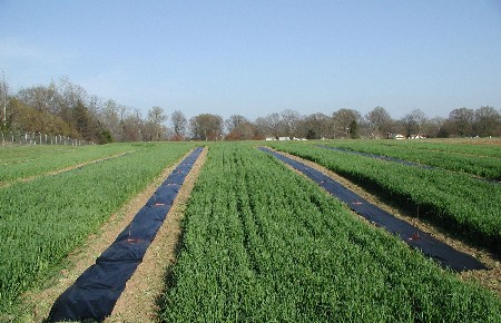
Topographical characteristics of area:
Topography is a major factor affecting irrigation, particularly surface irrigation. Of general concern are the location and elevation of the water supply relative to the field boundaries, the area and configuration of the fields, and access by roads, utility lines (gas, electricity, water, etc.), and migrating herds whether wild or domestic.
.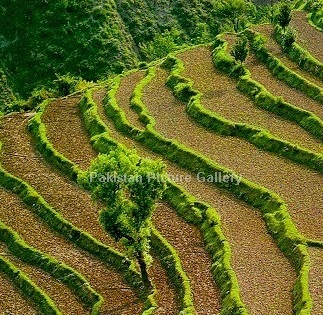
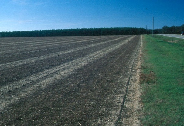
Field slope and its uniformity are two of the most important topographical factors. Surface systems, for instance, require uniform grades in the 0-5 percent range.
Restrictions on irrigation system selection due to topography include:
- Groundwater levels
- the location and relative elevation of the water source
- field boundaries
- acreage in each field
- the location of roads
- power and water lines and other obstructions
- the shape and slope of the field
Economics and cost of the irrigation method:
The type of irrigation system selected is an important economic decision.
Some types of pressurized systems have high capital and operating costs but may utilize minimal labour and conserve water. Their use tends toward high value cropping patterns.
Other systems are relatively less expensive to construct and operate but have high labour requirements.
Some systems are limited by the type of soil or the topography found on a field.
The costs of maintenance and expected life of the rehabilitation along with an array of annual costs like energy, water, depreciation, land preparation, maintenance, labour and taxes should be included in the selection of an irrigation system.
Main costs include:
- Energy
- Water
- Land Preparation
- Maintenance
- Labor
- taxes
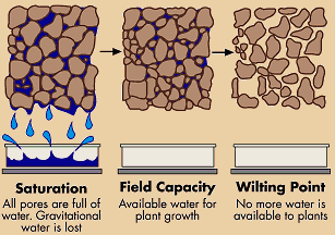
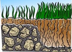
Soils:
The soil's moisture-holding capacity, intake rate and depth are the principal criteria affecting the type of system selected.
Sandy soils typically have high intake rates and low soil moisture storage capacities and may require an entirely different irrigation strategy than the deep clay soil with low infiltration rates but high moisture-storage capacities.
Sandy soil requires more frequent, smaller applications of water whereas clay soils can be irrigated less frequently and to a larger depth. Other important soil properties influence the type of irrigation system to use.
The physical, biological and chemical interactions of soil and water influence the hydraulic characteristics and filth. The mix of silt in a soil influences crusting and erodibility and should be considered in each design. The soil influences crusting and erodibility and should be considered in each design.
The distribution of soils may vary widely over a field and may be an important limitation on some methods of applying irrigation water.
The soil type usually defines:
- Soil moisture-holding capacity
- The intake rate
- Effective soil depth
Water supply:
The quality and quantity of the source of water can have a significant impact on the irrigation practices. Crop water demands are continuous during the growing season. The soil moisture reservoir transforms this continuous demand into a periodic one which the irrigation system can service. A water supply with a relatively small discharge is best utilized in an irrigation system which incorporates frequent applications. The depths applied per irrigation would tend to be smaller under these systems than under systems having a large discharge which is available less frequently. The quality of water affects decisions similarly. Salinity is generally the most significant problem but other elements like boron or selenium can be important. A poor quality water supply must be utilized more frequently and in larger amounts than one of good quality.
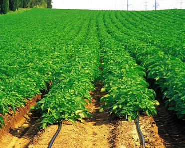
Crops to be irrigated:
The yields of many crops may be as much affected by how water is applied as the quantity delivered. Irrigation systems create different environmental conditions such as humidity, temperature, and soil aeration. They affect the plant differently by wetting different parts of the plant thereby introducing various undesirable consequences like leaf burn, fruit spotting and deformation, crown rot, etc. Rice, on the other hand, thrives under ponded conditions.
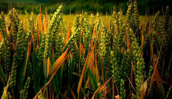
Definition of Cash Crops:
Some crops have high economic value and allow the application of more capital-intensive practices, these are called "cash crops" or Cash crop farming. Deep-rooted crops are more amenable to low-frequency, high-application rate systems than shallow-rooted crops. Examples of cash crops are Rice, Wheat, Seed Oils, Tobacco, cotton, sugar cane, etc.
Cash Crop Water Requirement
Crop characteristics that influence the choice of irrigation system are:
- The tolerance of the crop during germination, development and maturation to soil salinity, aeration, and various substances, such as boron
- The magnitude and temporal distribution of water needs for maximum production
- The economic value of the crop
Social influences on the selection of irrigation method:
Beyond the confines of the individual field, irrigation is a community enterprise. Individuals, groups of individuals, and often the state must join together to construct, operate and maintain the irrigation system as a whole. Within a typical irrigation system there are three levels of community organization.
There is the individual or small informal group of individuals participating in the system at the field and tertiary level of conveyance and distribution. There are the farmer collectives which form in structures as simple as informal organizations or as complex as irrigation districts. These assume, in addition to operation and maintenance, responsibility for allocation and conflict resolution. And then there is the state organization responsible for the water distribution and use at the project level.
Irrigation system designers should be aware that perhaps the most important goal of the irrigation community at all levels is the assurance of equity among its members. Thus the operation, if not always the structure, of the irrigation system will tend to mirror the community view of sharing and allocation.
Irrigation often means a technological intervention in the agricultural system even if irrigation has been practiced locally for generations. New technologies mean new operation and maintenance practices. If the community is not sufficiently adaptable to change, some irrigation systems will not succeed.
External influences:
Conditions outside the sphere of agriculture affect and even dictate the type of system selected. For example, national policies regarding foreign exchange, strengthening specific sectors of the local economy, or sufficiency in particular industries may lead to specific irrigation systems being utilized. Key components in the manufacture or importation of system elements may not be available or cannot be efficiently serviced. Since many irrigation projects are financed by outside donors and lenders, specific system configurations may be precluded because of international policies and attitudes.
(Courtesy: http://www.aboutcivil.org/)